Công ty Pitesco là nhà XNK hàng đầu và là nhà cung cấp chuyên
nghiệp các mặt hàng tự động, thiết bị điện và điện công nghiệp. Chúng tôi đáp ứng
mọi xu hướng công nghiệp hóa, hiện đại hóa cũng như mọi lĩnh vực.
Liên hệ cho chúng tôi theo số 0972 064 954 | 0914 237 179 để CÓ thông tin mà Quý
khách CẦN.
-
Mr Mai Nghĩa -
< Sales
Engineer>
Email : nghia@pitesco.com
Skype : nghia.pitesco
Product Description
Hysteresis Brake Dynamometers (HD Series) are versatile and ideal for testing in the low to medium power range (maximum 14 kW intermittent duty). With a Hysteresis Braking system, the Dynamometers do not require speed to create torque, and therefore can provide a full motor ramp from free-run to locked rotor. Brake cooling is provided by convection (no external source), by compressed air or by dedicated blower, depending on the model. All Magtrol Hysteresis Dynamometers have accuracy ratings of ± 0.25% full scale — depending on size and system configuration.
To better integrate dynamometers into systems, Magtrol offers both long and short base plates. The shorter base plate facilitates easier motor mounting when used with T-slot tables and Magtrol Adjustable Motor Fixtures, where as the long base plates are better suited for table top testing.
FEATURES
- 16 Standard Models with Maximum Torque from 2.5 oz·in to 500 lb·in (18 mN·m to 56.5 N·m)
- Hysteresis Braking System: Provides precise torque loading independent of shaft speed
- Motor Testing from No Load to Locked Rotor
- Accuracy: ±0.25% (Full Scale)
- Air Flow Sensor: For protection against overheating and operator error
- Standard Torque Units: English, Metric and SI
- Base Plate: Available in long or short versions
- Custom Dynamometers: for special torque and speed requirements
- Easy Calibration
THE HYSTERESIS BRAKING SYSTEM
All Magtrol Hysteresis Dynamometers absorb power with a unique Hysteresis Braking System which provides frictionless torque loading independent of shaft speed. The Hysteresis Brake provides torque by the use of two basic components – a reticulated pole structure and a specialty steel rotor/shaft assembly – fitted together but not in physical contact. Until the pole structure is energized, the drag cup can spin freely on its shaft bearings. When a magnetizing force from the field coil is applied to the pole structure, the air gap becomes a flux field and the rotor is magnetically restrained, providing a braking action between the pole structure and rotor.

Specifications and Drawings
| Model | Maximum Torque Range
(Metric) | Maximum Torque Range
(English) | Maximum Speed (rpm) | Kinetic Power - 5 Minutes (W) | Kinetic Power - Continuous (W) | Short Base Plate Downloads |
|---|
| HD-106-5C | 0.018 N·m | 2.5 oz·in | 30,000 | 35 | 7 | pdf | step |
| HD-100-5C | 0.08 N·m | 11 oz·in | 25,000 | 75 | 20 | pdf | step |
| HD-400-5C | 0.28 N·m | 40 oz·in | 25,000 | 200 | 55 | pdf | step |
| HD-500-5C | 0.85 N·m | 120 oz·in | 25,000 | 400 | 80 | pdf | step |
| HD-510-5C | 0.85 N·m | 120 oz·in | 25,000 | 750 | 375 | pdf | step |
| HD-505-5C | 1.7 N·m | 240 oz·in | 25,000 | 800 | 160 | pdf | step |
| HD-515-5C | 1.7 N·m | 240 oz·in | 25,000 | 1,500 | 900 | pdf | step |
| HD-700-5C | 3.10 N·m | 440 oz·in | 25,000 | 700 | 150 | pdf | step |
| HD-710-5C | 3.10 N·m | 440 oz·in | 25,000 | 1,500 | 935 | pdf | step |
| HD-705-5C | 6.20 N·m | 55 lb·in | 25,000 | 1,400 | 300 | pdf | step |
| HD-715-5C | 6.20 N·m | 55 lb·in | 25,000 | 3,400 | 3,000 | pdf | step |
| HD-800-5C | 14.00 N·m | 125 lb·in | 12,000 | 2,800 | 1,800 | pdf | step | t-slot base |
| HD-810-5C | 14.00 N·m | 125 lb·in | 12,000 | 3,500 | 3,000 | pdf | step | t-slot base |
| HD-805-5C | 28.0 N·m | 250 lb·in | 12,000 | 5,300 | 2,250 | step | t-slot base |
| HD-815-5C | 28.0 N·m | 250 lb·in | 12,000 | 7,000 | 6,000 | pdf | step | t-slot base |
| HD-825-5C | 56.5 N·m | 500 lb·in | 8,000 | 14,000 | 12,000 | pdf | step |
Note: Operating at the continuous power rating for periods of up to 4 hours is acceptable. However, operating for extended periods at high temperatures will result in premature component and bearing failure. Limiting the length of the cycle and the component temperatures will guard against premature failure. Where continuous duty is desired for longer time intervals, component temperatures should be maintained less than 100°C; monitoring the outside brake surface temperature is a sufficient reference.
Contact Magtrol for 6N (English), 7N (Metric) and 8N (SI) Specifications
Blower Dimensions
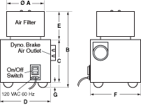
Allow approximately 6 in to 8 in (152 mm to 203 mm) between rear
of dynamometer base plate and blower for connection hardware.
Required hardware is supplied with the dynamometer.
| Model | BL-001
(in) | BL-001
(mm) | BL-001
(in) | BL-002
(mm) |
|---|
| ØA | 6 | 152 | 6 | 152 |
| B | 11 | 279 | 11 | 279 |
| C | 6 | 152 | 6 | 152 |
| D | 8 | 203 | 15 | 381 |
| E | 4 | 102 | 4 | 102 |
| F | 8 | 203 | 12 | 305 |
| G | 1 | 25 | 1 | 25 |
| Weight | 8.5 lb | 3.9 kg | 18 lb | 8.1 kg |
Blower Power and Fuses
- Models HD-710, HD‑715, HD-810 and ED-715 include the BL‑001 blower.
- Models HD‑815 and ED-815 include the BL‑002 blower.
- Model HD‑825 uses two BL‑002 blowers for cooling its two brake sets.
| Model | Voltage | VA | Style | Rating |
|---|
| BL-001 | 120 V | 600 | UL/CSA | 6.30 A | 250 V | SB |
| BL-001A | 240 V | 500 | IEC | 3.15 A | 250 V | T |
| BL-002 | 120 V | 1,000 | UL/CSA | 15.00 A | 250 V | SB |
| BL-002A | 240 V | 1,000 | IEC | 6.30 A | 250 V | T |


